
Composite Materials Technology: An Expert Interview with Designer Lapo Ancillotti
Interviewed by Dave Rearick, Skipper of Bodacious Dream
Dave Rearick from Bodacious Dream conducts an in-depth interview with designer and materials specialist Lapo Ancillotti on the subject of the evolution and current state of composite fabrication materials used, among a variety of purposes, in building new racing boats. (At the bottom of this page, there is a video clip of a portion of this extended interview.)
See two other expert interviews Dave has conducted:
:: Sailing Navigation – interviews w/ John Hoskins & Matt Scharl
:: Rigging Technology – an interview with Alan Veenstra
:::::::::::::::::::::::::::::::::::::::::::::::::::::::::::::::::::::::::::::::::::::::::::::::::::::::::::::::::::::::::::::::::::::::::::
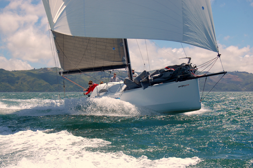
I recently got the chance to catch up with my friend Lapo Ancillotti in Wellington, New Zealand where I stopped on my solo circumnavigation of the globe on Bodacious Dream, the Kiwi 40 FC racing sailboat, which Lapo saw through from design to finished construction to testing right there in Wellington. Lapo is a specialist in composite technology having built many boats as well as aircraft with composite materials and has also taught at the post-graduate level. Here is a transcript of my interview with Lapo that covers the fascinating area of composite technology.

Dave Rearick (DR): Lapo, you’ve been involved in designing and building boats for many years – since you were a young man as I recall. The world of boat building has changed tremendously over the past 50 years, and most of that change has been driven by the desire for lighter and faster designs, which have been made possible by the developments of new materials that we generally refer to as “composite construction.”
When I was a kid, some 45 years ago, the first fiberglass boats were showing up in the world but composite construction wasn’t limited to just boats. I saw many things that involved fiberglass from bathtubs to camper trailers, but also I remember carbon fiber being used in fly fishing rods and tennis racquets. The areas now where composites are used are huge. What are some other interesting items that use composite technology for their construction?
 Lapo Ancillotti (LA): Along with boats, there are now an increasing number of additional applications for composite technology. Actually, every sector of the industry has appreciated the enormous upside gain of using composite technology. The strict definition can be a little fuzzy, as it includes different materials and different construction methodologies specific to the nature and the technical requirements of the article being manufactured. Today, composites are the leading technology for aviation (military and civilian, commercial and research sectors), the car industry, as well as pushbike and motorbike – piston and electric engines, skiing, wind generation, specialized casings, construction (strengthening and components), medical (prostheses), boats in every sector, including kayaking, surfing, America’s Cup, military, sailing, accessories for climbing, cameras, racing of any kind, and many more. In a few words, everything that requires being stronger and lighter would be a possible candidate for composite and carbon fiber.
DR: Can you explain what basics composite construction is?
LA: Conventional fiberglass is an assembly of cloth and polyester resin. Before processing, the resin is in a thick liquid and somewhat sticky state. When mixed with a chemical component called hardener, the resin starts a chemical process of “solidification” and turns into a solid, hard block of plastic. This resin, when used in combination with the cloth soaked in it once cured results is a strong laminated sheet.
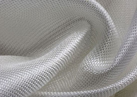
The fiberglass cloth is made of glass filaments, and is very flexible, making it easy to adapt to different surfaces and angles. The difference between a fiberglass laminate and a similar sheet of metal or wood is the ability to be shaped in a complex, multiple sided and double curved surfaces, without the need of a multiple assemblies.
The basic process is to lay up a layer of glass on top of a surface or mold prepared with a “release agent.” The cloth is impregnated using a brush with the mixed resin. You wait the cure time and then release the “article.” The article would reflect the shape of the prepared surface. If the surface is flat the article is flat, if the surfaces is complex, like the inside of a sink for instance, the article will reflect the shape of the sink inside. The surface of the new piece that is next to the mold will be as smooth as the mold while the other side will be as smooth as the ability of the technician to use the brush and the roller.
However, according to the expected characteristic of the article and its required strength, several layers and combinations of different cloths might be used, as well as different technologies developed to “preg it by brush”, to improve the efficiency of the resin impregnation process.
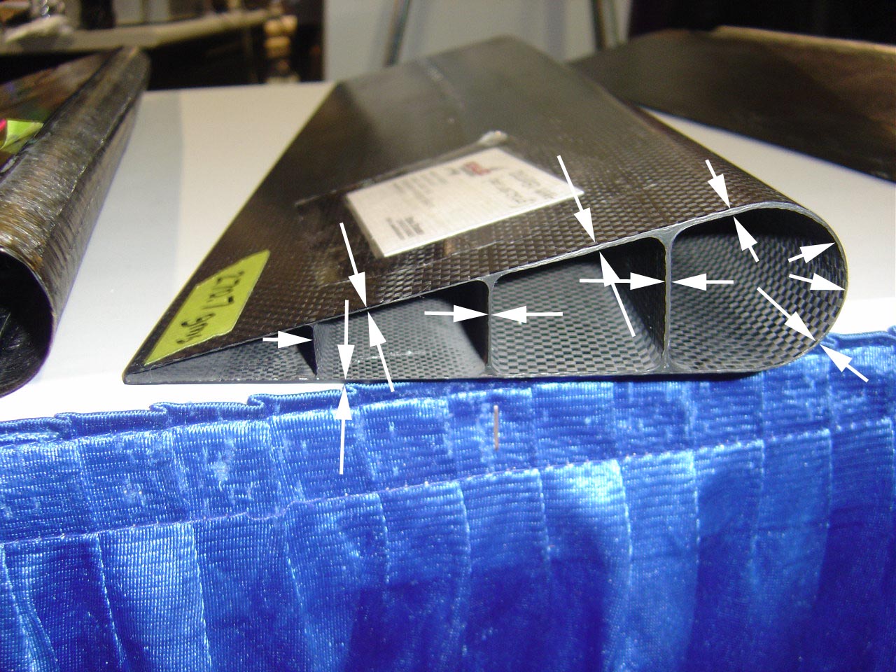
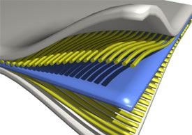
 In the later 1930’s, a British aircraft manufacturer company called De Havilland developed a new concept for making such panels even stronger. They started by gluing two skins – one outside, one inside and a core in between them, making the panel thicker and thereby stronger. The skins were very thin and made of a very strong material while the core was very thick (20X the width of the outer skins) and made by using a very light material. Once the glue was cured, the three layers formed one solid and lightweight block. De Havilland used plywood for the outer and the inner skin, and balsa for the core. They built a twin-engine fighter plane called the “Mosquito,” by using what was later called “sandwich structure” (skins + core). Different molding technologies were developed to produce curved sandwich panels. The Mosquito was stronger, lighter, and faster than any twin-engine war fighter of the same generation.
Later on, the sandwich structure was more widely adopted and became the state-of-the-art for composite constructions. But instead of plywood and balsa, the skins were made of cloth, and the core was made in balsa or foam and a mixture of resin and hardener was the glue.
DR: We’ve all heard the term fiberglass, which was one of the earliest materials to use composite construction. Is it really fibers of glass? Isn’t that glass breakable? What changes to make it so strong?
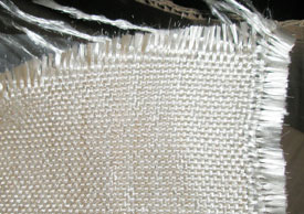 LA: Originally, it was only filaments of glass woven together and turned into a cloth with 0 and 90 degrees layout of the fiber weaves. That’s why the name fiberglass – fiber made by glass – which became the early common definition for composite. A tiny fiber line is a few microns in diameter, and when hundreds of such lines are assembled together to form an assembly of a few millimeters in diameter, the glass develops a significant resistance to pulling. When the above assemblies are woven to create a cloth, it turns out to be an unusually strong piece of fabric, which becomes a very resistant sheet once impregnated with the resin, which serves to “encapsulate” the glass. Multiple layers of impregnated “preg” fiberglass will be laid up to create a freestanding structure, such as the hull of a boat or the body of a car. The final product will be a strong and stiff component, despite the fact that the original filaments of glass were single elements, tiny and weak.
DR: What other materials are used in composite construction these days.
LA: Since the early days when only glass was available, new materials have been developed. Due to the flexibility of the composite technology, the industry started to explore and to widen the field of potential applications. The first step was to improve the mechanical characteristic of the resin, so they started developing new resins that would behave with more stability than the original polyesters, which were and still are very prone to shrinkage. Vinylester resins became common in the market beginning in the late 70’s. This was followed by the development of the epoxy resins, which were far more resistant and structurally stronger than vinylester. Epoxy resins became available from about the mid-80’s – though not so common then due to their high price, though the military has used them since the late 60’s. Early in the 90’s epoxy became more affordable, which meant it was widely used for high-tech production, leaving polyester to be used for low-tech production.
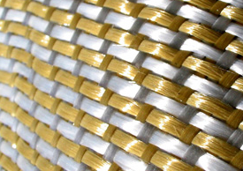 Cloths evolved too; Synthetic fibers – including the now widely known carbon fiber (graphite-based fiber) or Kevlar (para-amidic synthetic fiber) – were much stronger and lighter than the glass-based fabrics and when used in association with the new resins, had a formidable strength-to-weight ratio compared to the glass fibers, although they were significantly more expensive. You may know that Kevlar is used for bulletproofing!!
When the above new fibers are combined with the newer epoxy resins, they form what we today refer to as “composites”. Such current composite structures are stronger and lighter and have a very high heat tolerance too. In other words, it is a very stable and highly reliable long-term product that is also more resistant to deterioration over time than the older polyester and glass fiber.
DR: What types of “coring” materials are used and what makes them particularly good for different applications?
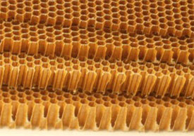
LA: Let’s go back to the concept of the sandwich structure. Here as with the resins and the cloths, the “core” was also taken to a higher level. From, Different types of foam – mostly PVC based, began to the original balsa with denser and stronger materials like phenol, aluminum, and even titanium. These materials were used to create a so-called “honeycomb” structure – a sort of big cell sheet with high compression capability -, which improved both the weight and strength upon the earlier sandwich structures.
 A foam sandwich is relatively low-tech compared to a honeycomb sandwich. However it is more affordable and it will still be used where high-performance is not required. Foam sandwich would be simply too heavy and weak for a Formula One car say, or for military specialty jet… just as a honeycomb sandwich wouldn’t be justified in the construction of a cruising yacht.
DR: So these cloth-reinforcing materials combined with the core and a resin are put into a mold and then forced into the shape. I suppose that much is not so different from like paper maché´, but there is a difference in that now vacuum pressure is used to help form the product. How does that work and what does it do?
LA: Correct. The reinforced laminate – resin + fibers combined with the core – are molded in a step-by-step procedure. Once you have created the mold – a “female” recipient of the shape you want to achieve – the process of layup – laminating will happen inside. Outer skin first, then core, followed by the inner skin. In order to compress the fibers and the core together, to compact the layers, it is common practice today to put a vacuum bag on top of the laminate. This plastic bag is sealed at the edges against the flanges of the mold, using a vacuum pump. Then the air is sucked out of the layup, before the resin starts gelling and hardening. This assures the proper shape as well as minimal excess resin, which reduces weight and increases strength.
With the introduction of multiple-molding technologies – molding independent components together – undercuts became possible, allowing complex geometries to be made in one single piece without joints.

DR: I’ve heard the term “prepreg.” What does this refer to and how does it help in facilitating the composite construction?
LA: Initially, the layup and preg laminating process had to be manual performed. Later on, machines were used to “prepreg” the fibers in order to improve the efficiency of the process and the mechanical characteristic of the laminate. The combination of the epoxy resin and the new core materials, combined with the new technologies of “prepreging.” made it possible to control the exact amount of resin required to achieve the optimum percentage for the best weight to strength ratio.
The resin used to prepreg the cloth is already mixed with the hardener and it is near ready for curing, but is kept in a sticky state by storing it in a very low temperature environment: like a freezer.
Here we need to come back for a minute, and to spend a little time explaining how the resign goes from a fluid state to a block of hard plastic.
 As anticipated, once the hardener agent is added to the liquid resin, the chemical reaction process of the resin begins “kicking off” – i.e. gelling – but it’s becoming solid depends on the temperature. In a very low temperature, the process of gelling simply doesn’t happen. You need to go over 20 degrees C to start the chemical reaction, and sometime up to over 100 degrees C to complete the curing process. Every different type of resin requires a different temperature to be cured. If the curing temperature is too high or too low, the final mechanical characteristic of the resin won’t be as strong as specified by the manufacturer.
Coming back to the prepreg, the sheet will layup into the mold, and the mold will be moved inside an oven called an “autoclave” and there heated up. Also the time required to raise the temperature to the curing target is fundamental to success; this is called the “temperature ramp” process. The prepreg technology guarantees a very tight control of the weight and strength but only so long as the curing process is properly managed.
DR: You mention an autoclave, what does that look like and what does it do?
LA: The more the laminate is compressed, the stronger it becomes. Since the early days of epoxy, the hand laminated was vacuum bagged to squeeze the residual air out of the laminate, and, even more importantly, to compress the different layers and to improve the strength of the laminate.
The prepreg sheets are more compact than the hand-laminated layers. The resin is equally distributed and the more you compress it, the stronger the laminate will be.
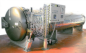 There are different ways to do the bagging and to vacuum a laminate and make it ready for curing. The autoclave is the most efficient, and the most expensive way to do this. The autoclave is a tank where you store your mold with the laminate in it, ready for curing. Being a closed steel tank, like a huge gas bottle, the pressure on the laminate inside the autoclave can be taken to a much higher level than what you can get with a simple bag and a vacuum pump. The higher the pressure, the hotter the temperature inside the autoclave will become. So the autoclave guarantees the best possible combination of applied pressure on the laminate and the optimum curing temperature.
However, a steel tank engineered to handle such huge pressure and big enough to hold the mold of a racing yacht or the fuselage of an airplane inside it is very expensive and not very common. Therefore the autoclave is justified only if significant investments are involved. They are somewhat more common for smaller pieces of high-tech equipment or say for the mast of a sailboat.
DR: Do you use computers in the designing and shaping process for the boats and airplanes?
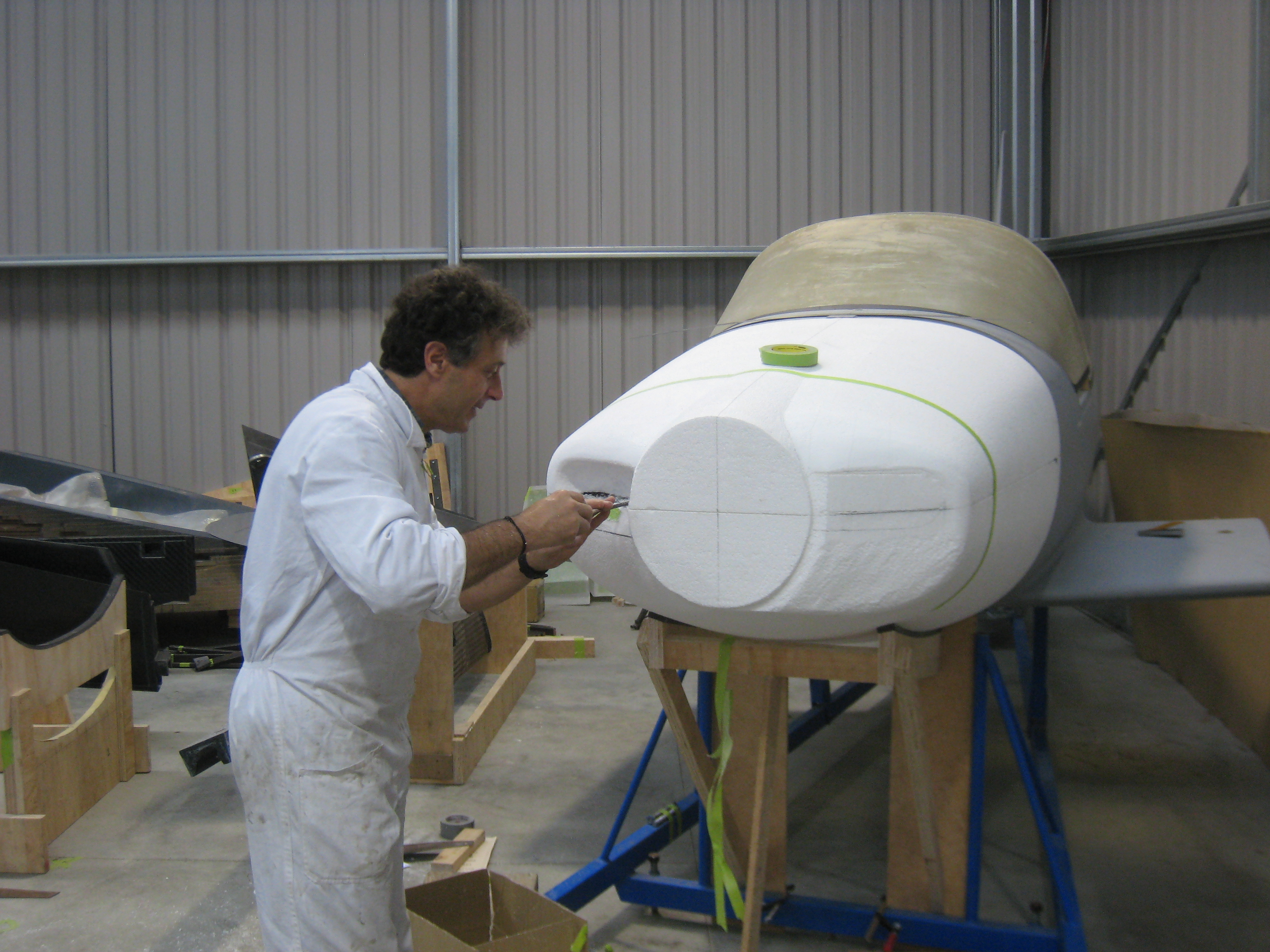
LA: Only a few years ago, the process was to make a “male” plug of the article in its actual dimension by hand, and to form and make the “female” mold around it. The process of completing the plug was very labor intensive, and the precision of it was very much dependent on the skill of the builder. Today the plug can be machined by a CNC router, when a plug is required or when a CNC machine female mold is not practical – say, for example, when an article is 100’ long.
In fact, lately, female molds of small dimensions – up to a few meters in length – can be formed using CNC router robot machines, which replicate the shape of the article to be manufactured by milling the “negative recipient” directly from a 3D model computer file.
Furthermore, the latest technology for making very small female molds now includes 3D printing as well. This is a machine that lays up a plastic model of an article from a 3D computer file applying a very thin layer of plastic at each pass… until the final product is produced. This is a suitable technology for light articles and prototype production only, at least until new material like “printed carbon fiber” become available – which might be happening soon… as experiments are already under way!
For production of big articles, 3D printing won’t be a substitute anytime soon for the CNC router, but it signals the arrival of an amazing technology that will make it possible to develop new solutions and concepts on a smaller and more economical scale before committing to the real thing. 3D computer files can be very easily be scaled up or down.
DR: So all of that comes together to produce these composite products. I suspect the possibilities are endless… yes?
 LA: If you look at the technologies we have discussed here and the multiple combinations that exist between them, we can easily say that the limit is only your imagination. I mean that today you may have an idea, a particular layout in mind, a shape – any shape really, a solution and, as long as you are able to turn it in a 3D file, you can:
- Sketch it
- 3D print it and see what it looks like
- Explore different solutions
- CNC machine your mold or plug using the final 3D model file
- Manufacture your article in carbon prepreg and post cure it in autoclave
- Or if you like, you can go for any of the lower tech and mid-step solutions available, depending on the budget.
However, let me say this … there are no shortcuts to quality. It is fundamental to develop your skill in understanding the principle of volumes, in learning basic hand sketching and hand modeling by foam, tooling board, wood, etc.
A designer’s goal is to create a direct link between your imagination and the physical word, in the way that you accomplish your goals. Without the above skills, you won’t be able to tell the computer entirely what you want. You will only follow what the computer tells you can be done… according to its logic, not your own. The computer does not have imagination. Ultimately, it is your skills and imagination that make the difference.
DR: Of all the interesting projects you’ve worked on and taught students, what would you say was the most interesting experience you had?
LA: In some way, all the projects I have been involved with have been interesting. Every one represented some kind of step forward. About 35 years ago, I came up with the idea of creating a frame to support a superlight foredeck on a small sailing dinghy (LOA 4.4 mt.) I designed it. Then I worked for an entire week, assembling the frame under the deck level after which I joined this nearly nonexistent and very thin, deck to the hull. I was quite proud of the only 2 or 3 kg of the weight of that deck area. However, when I put the rig on and started pulling the mainsheet, the entire foredeck turned into a rippled plane. Simply, the frame cage didn’t move at all, but the plane on top of it could not hold the compression of the forestay and the entire forward area came apart. I was still very young, I was just experimenting, the project didn’t go any further, but I learnt so much out of it!
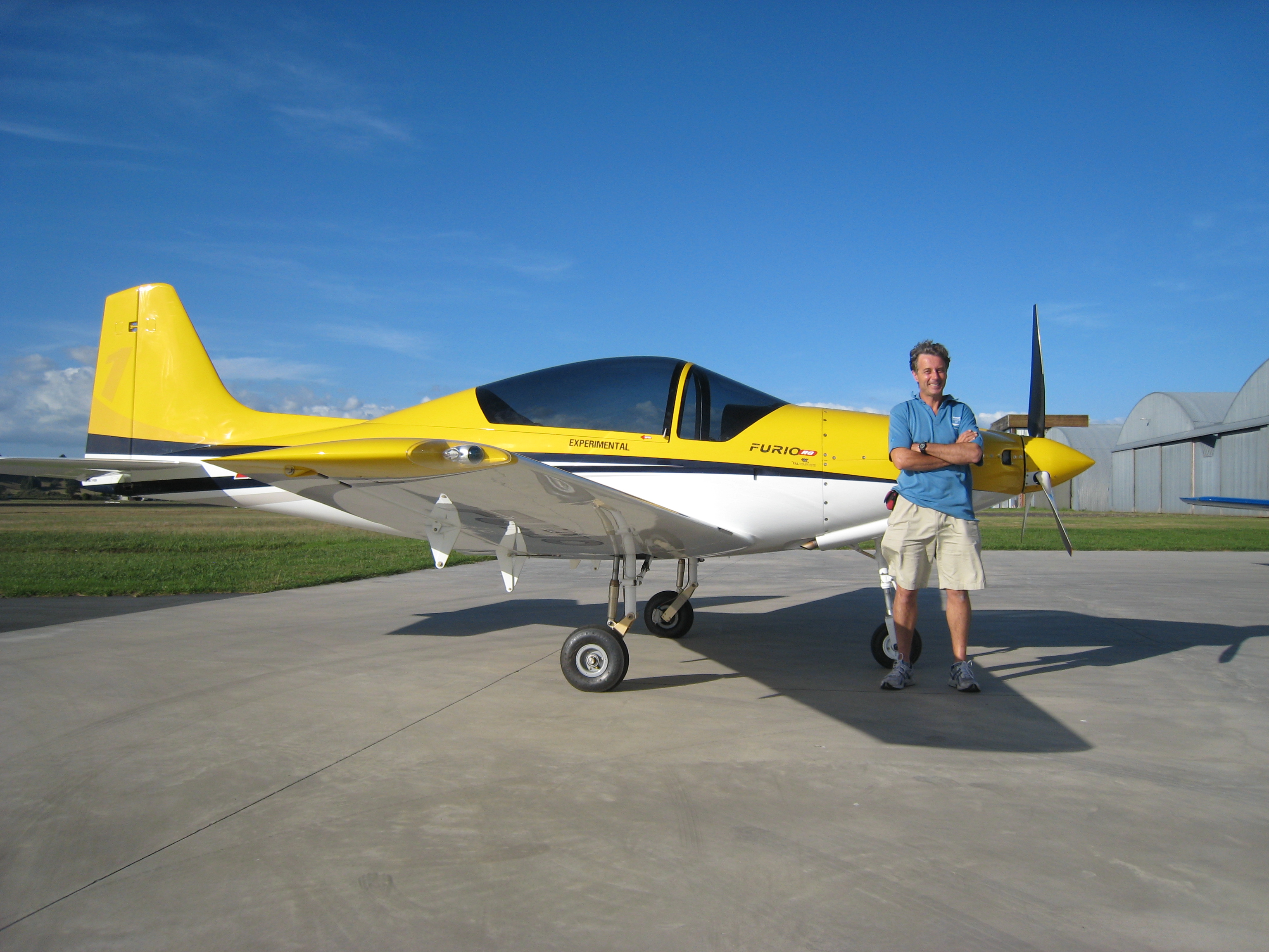
Another time, I conceived the structure of a wing of an airplane in a totally different way from anything I had seen before. To arrive at this, I took into consideration all I had learned in the previous 35 years, including that dinghy’s deck and the problem I had with that tiny single skin. Although people were skeptical, the proposed design of the wing – and the other components of the airframe – worked very well. The airplane had its maiden flight after 20 months of design and construction, and its wings proved to be extremely strong. The purpose of that project was to reduce the number of parts, so to reduce the labor and to optimize the weight distribution, all of which we achieved. That project was awesome.
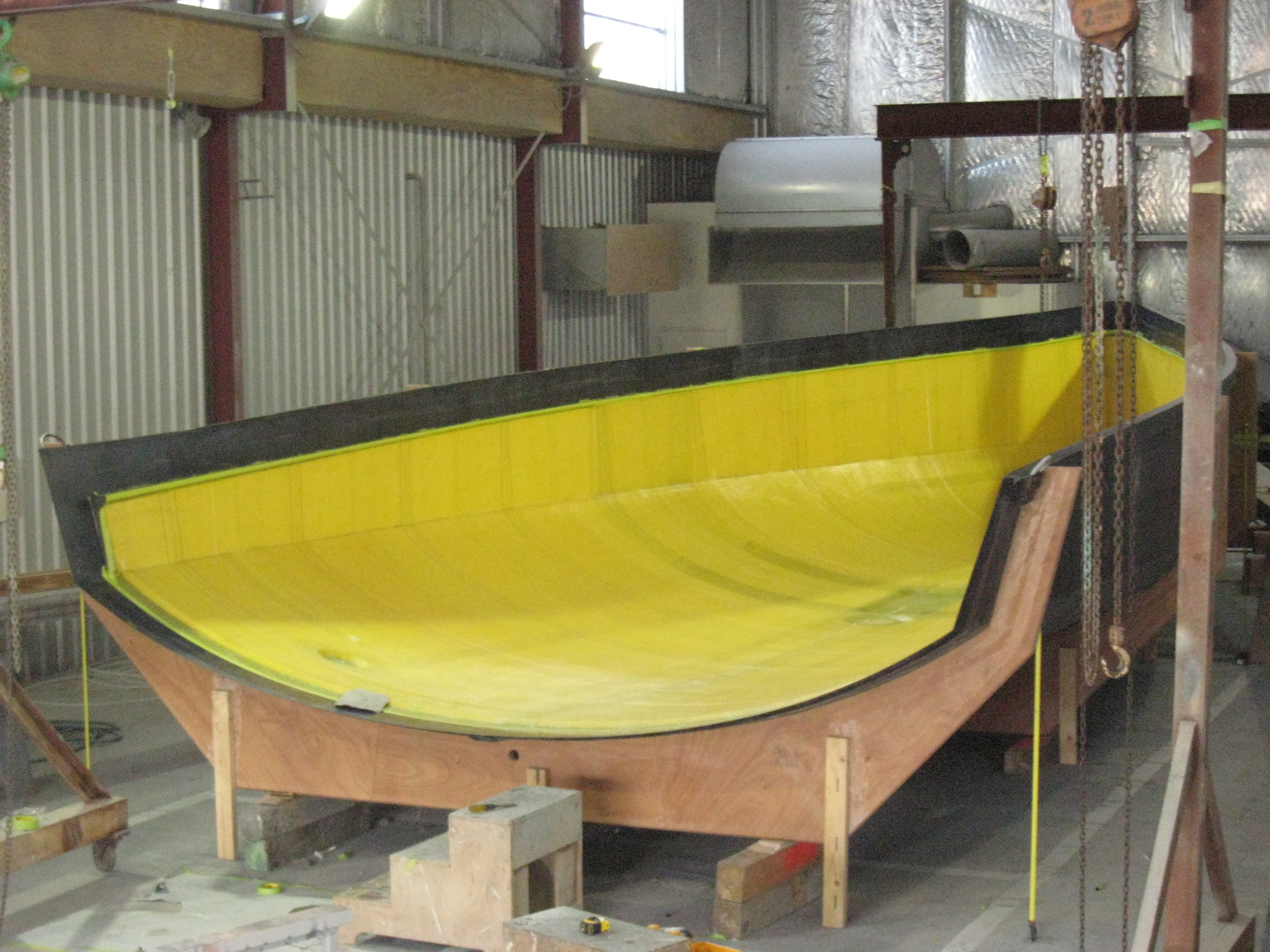
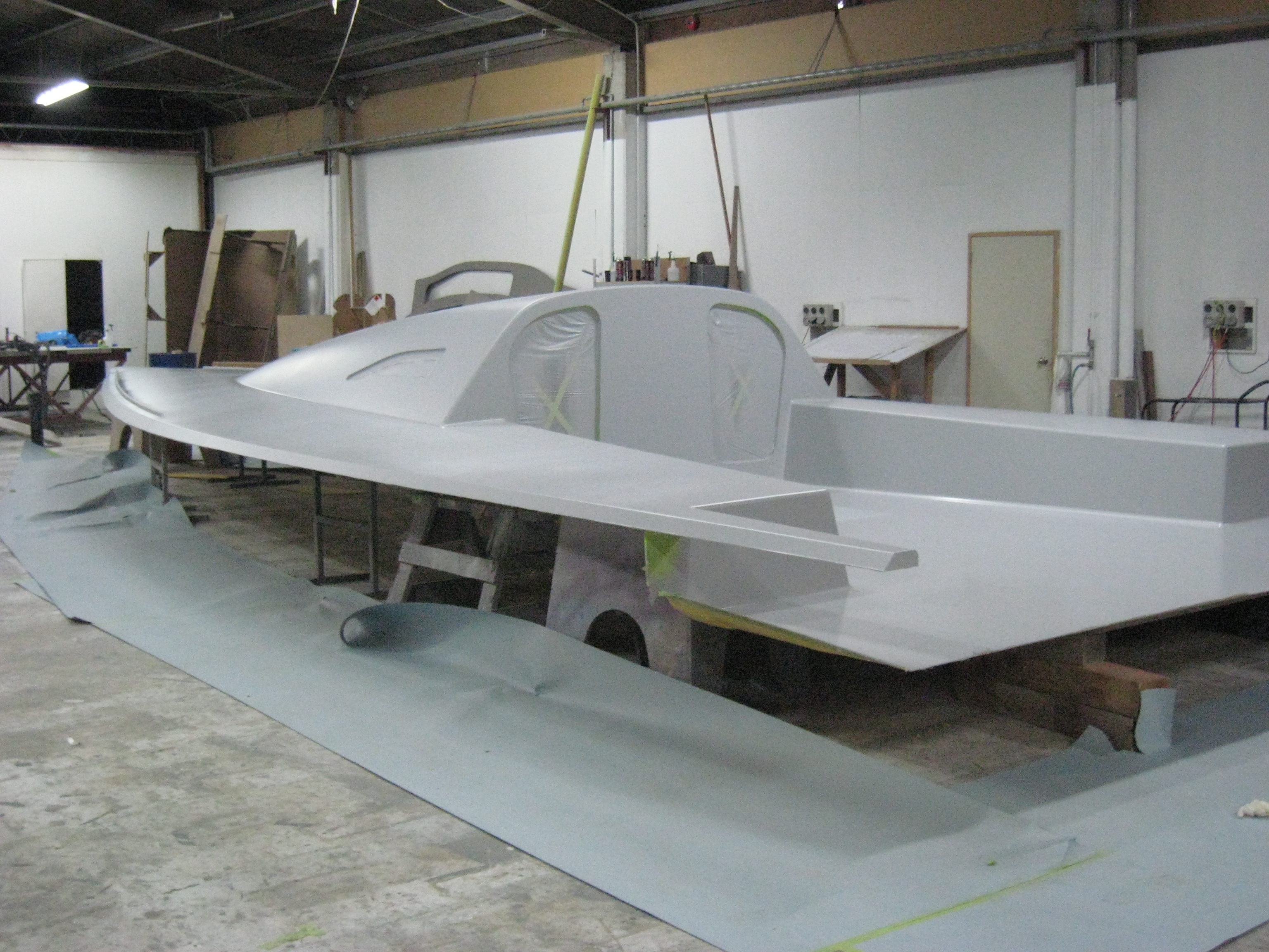
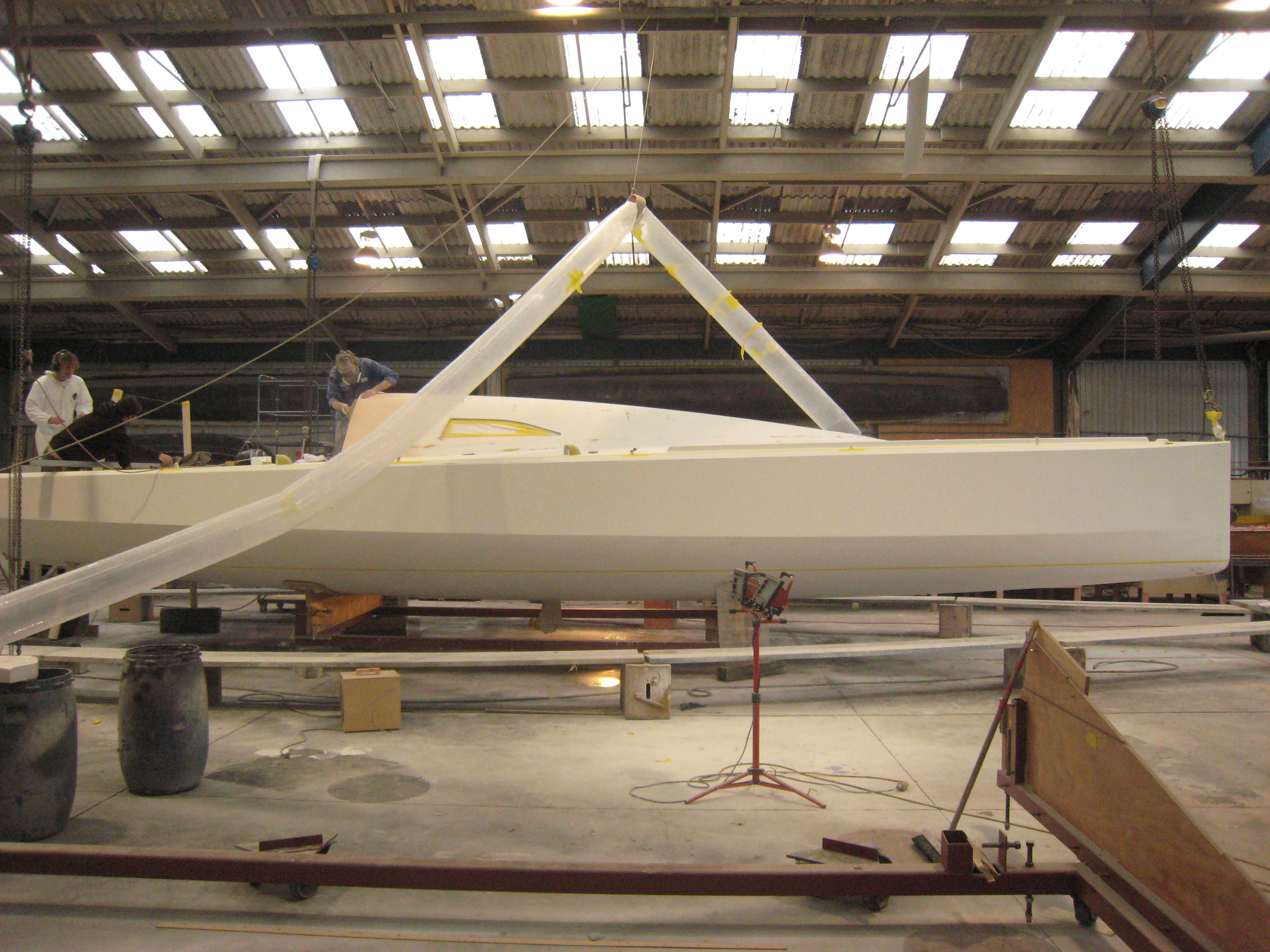
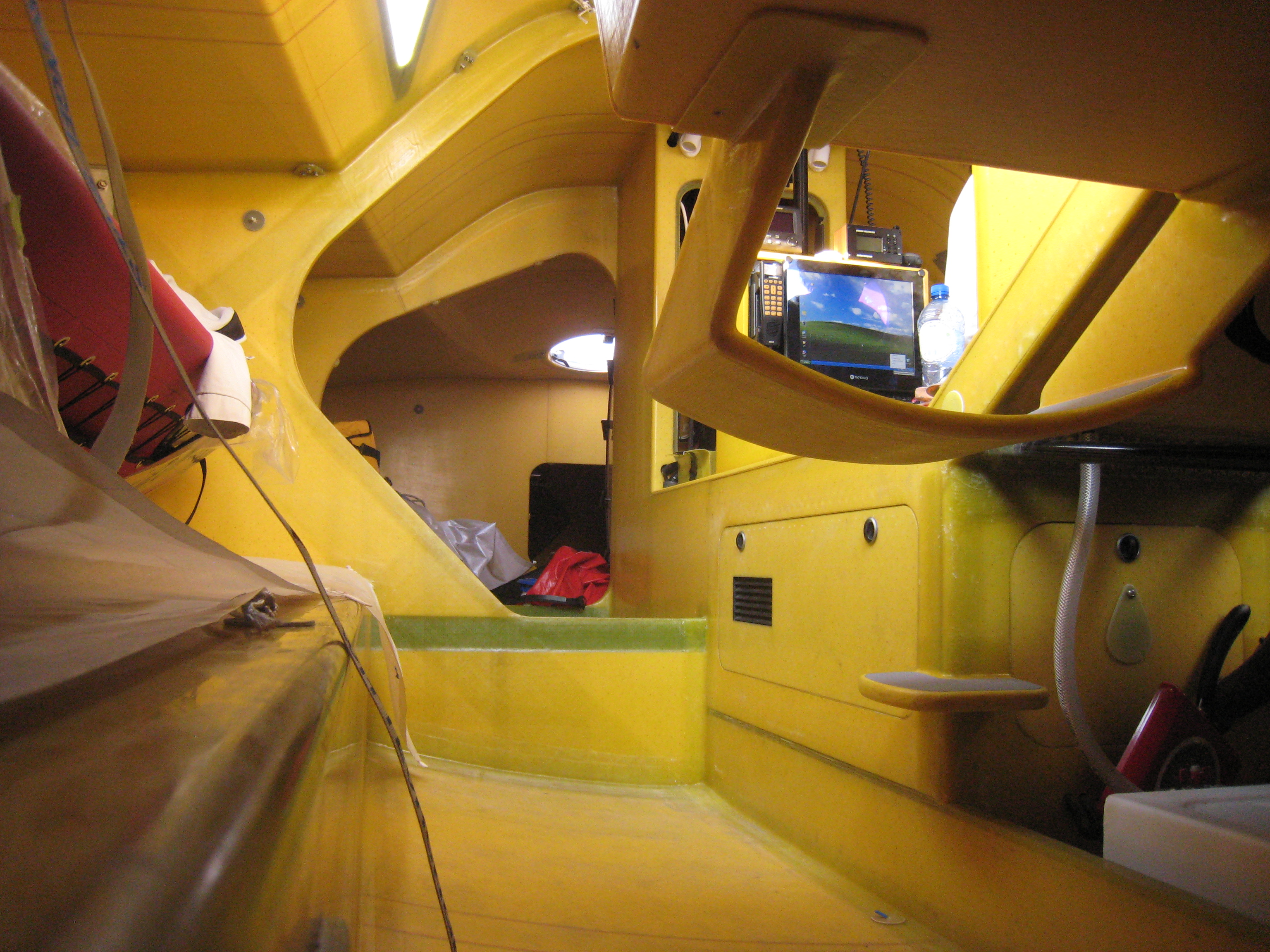
The Kiwi 40 and in particular Bodacious Dream, was an interesting project too. Farr Yacht Design designed the boat and Bruce Farr was personally involved in the design concept definition. I told them my thoughts on how we could bring the Class 40 design to a next step. When we met at the Farr Yachts design office in Annapolis, the Class 40 designs were all pretty much optimized for specific conditions. The whole Team at Farr Design did a superb job in developing a totally new design, and they made the Kiwi 40 the first truly all-around Class 40 designed. Once again, we developed a different approach to the design of the layout and to the construction of the structure. The result was the stiffest Class 40 ever launched. Interesting enough, the Class 40 rules limit the use of expensive materials, so carbon fiber is banned for the hull, deck and structure construction. Because of it, we were forced to be creative rather than simply looking for more expensive materials and solutions. Therefore, we decided to focus on optimizing the weight distribution in order to lower the center of gravity (CG) as much as we could, and we concentrated the weight as close as possible to it to reduce the inertia.
But overall I’d say one of the most interesting things I have experienced in my life was to work as student projects supervisor and student mentor at the Wellington Institute of Technology. My role as a technologist was to introduce composite material expertise into the R&D department. I find working with young people extremely stimulating. They are totally motivated by new ideas. Even when encountering new developments, I was impressed by the speed at which new concepts were absorbed and put into practice.
Other favorite projects included an underwater vehicle, a lightweight electric motorbike, a small wind turbine to be used as generator in light airplanes, as well as composing lectures on the principles of the 3D computer modeling and running workshops on the use of composite materials.
It was great to see how much the student improved the stiffness of the carbon fiber frame of the electric motorbike we made by changing the layout of the structure and in doing so; we made it simpler and easier to build as well. On that one, the tool we used was the Finite Element Analysis (FEA.) If you combine the FEA with the Computer Fluid Dynamic CFD) – you will optimize the drag as well, which is what we did at Farr Yacht Design when we designed the Kiwi 40.
Burt Rutan is the most creative and innovative composite airplane designer of the last 40 years. He said: “If you know that it is going to work, there won’t be research.”
Burt was a role model for me. I wanted to explore new things. And that’s what creative young people are extremely good at. Don’t listen to the people who tell you that it is not going to work. They may be right, but don’t be afraid to prove them right by trying your idea! Then again, they may be wrong, and you may be right. Make sure you cultivate your curiosity, your imagination, your attitude toward understanding the problem first and then clearly identifying what you want to achieve.
And, still according to Burt, it is very important that you embrace the concept of: “It’s got to be fun!”
DR: Wow, there are so many wonderful ideas there Lapo! As for me, being on the receiving end of your talents by having you create Bodacious Dream and then having sailed her for over 40,000 miles around the world, I can see the future of composite technology is boundless. One last question… what can you see coming in the future that will make my next boat even stronger and lighter?
LA: If the goal was pure speed, she should be much more aerodynamically efficient than what you see out there today. She should be built with fewer parts thereby increasing the integration between the structural elements. Probably the way to manufacture her would be by employing according new CNC technologies and by creating multiple molds in order to get rid of those hull-deck joint and to make them all flow together as one.
DR: Thank you Lapo! That was a truly bodacious learning expedition!
Excerpts from Dave’s Interview with Lapo Ancillotti